Review of the MSI MS-7504 VER:1.1 motherboard
Part 1 - Part 2
This motherboard was installed in the branded PC Fujitsu Siemens AMILO Pi 3645 - I will describe it separately. I didn’t get it completely complete... and there are problems with the motherboard itself... Therefore, we describe what it is and how it is.
+ Click on photo to enlarge!
Surprisingly, this motherboard is not on the manufacturer’s website... that’s why there are problems finding drivers. In the first part we will describe the motherboard itself. And in the second part we will get acquainted with the BIOS settings and its operation in general...
Let's examine the motherboard from the outside
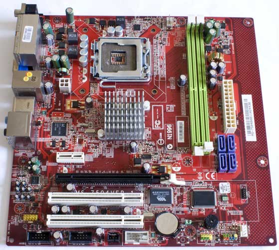
This is a typical small motherboard, square - 245 by 245 mm, Micro-ATX form factor. Eight mounting holes. The color of the PCB is red or dark cherry. At first glance, the arrangement of the elements is normal, standard: in the upper part, approximately in the middle, there is a processor socket, memory slots to the right... regular power connectors... chipset heatsink... SATA connectors, then connectors for expansion cards...
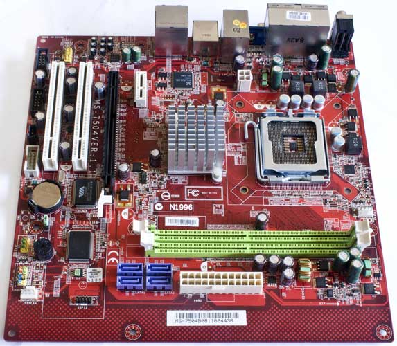
But what immediately catches your eye is the empty strip of PCB on the left side of the board, 23 mm wide. Why is it needed? Really for the sake of three mounting holes? Next, the motherboard is from 2008-2009, but it does not have IDE and FDD connectors... only four SATA. But in those days, hard drives and optical drives with an IDE interface were very relevant and widespread! And even floppy drives were still in use. Moreover, the chipset ensures the operation of one IDE connector for two devices... We also immediately note that this is a single-chip motherboard. Those. there is one system logic chip and there are no North and South bridges. Let's take a closer look at the individual parts and elements.
LGA775 on MSI MS-7504
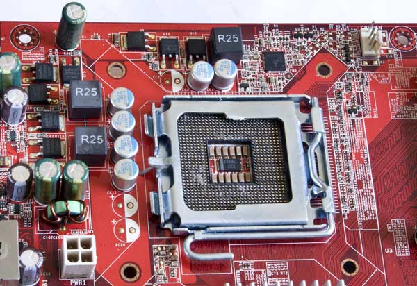
The processor socket is standard LGA775. A three-phase power supply system is located around it in the letter G. It consists of solid-state (?) capacitors, three chokes in square ferrite cases. MOSFET transistors NIKOS P70N02LDG and NIKOS P0903BDG.
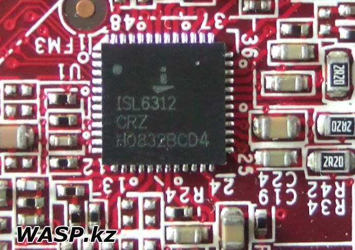
This is controlled by the Intersil ISL6312 PWM controller. We immediately see a 4-pin connector for connecting a processor cooler, which means you can adjust the fan speed (this is good).
RAM
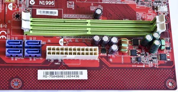
Upper right corner of MSI MS-7504 motherboard. There are two slots for DDR2 RAM with frequencies of 533/667/800 MHz. The maximum supported memory size is 4 GB. Alas, the memory only works in single-channel mode. We immediately see the 24-pin motherboard power connector (an additional 4-pin one just below and to the left of the processor socket). There are also power supply circuits for the memory and the entire motherboard. We already see ordinary electrolytic capacitors, ordinary toroidal chokes, MOSFETs - P45N02LDG and a pair of P0903BDG. The mP6103S8 chip is a step-down DC-DC converter. Another chip with the Winbond W83310DG logo is a linear voltage regulator. Four SATA revision 2.0 connectors (up to 3 Gbit/s).
MSI MS-7504 lower right corner
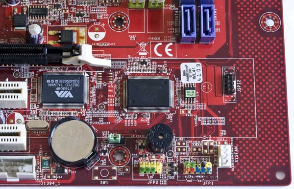
Let's go down and look at what's here - the lower right corner. Here we see a battery that saves all BIOS settings. Nearby there is a jumper to reset these settings (if you are too lazy to take out this battery). The BIOS itself is a small U19 chip and has a green sticker on it indicating the firmware: A7504 NF130N. Nearby is the obligatory BIOS sticker. Two large microcircuits: one VIA VT6308P - this is IEEE 1394 or Firewire (in those days it seemed that the prospects with this bus were huge, alas, it did not come true). The second microcircuit with a paper sticker, under which we see the marking Fintek F71882G and this is a multifunctional controller Super Hardware Monitor + LPC I/O... for example, it provides IEEE 1284 or LPT... FDC - floppy operation... all this is missing. Support for keyboard...mouse...monitoring of temperature, voltage sensors, etc. We immediately see a soldered speakerphone and a group of JFP1 contacts for connecting an external speakerphone and Power LED - it’s not clear why this is needed? After all, there is already a JFP1 standard group of contacts for connecting elements of the front panel of the case - the power and reset buttons, the power indicator and hard drive activity. Another 4-pin connector for connecting an additional cooling fan... There is also a 9-pin group marked on the JSPI2 PCB - it is not described in any way in the manual. This is for connecting the programmer and BIOS firmware in MSI motherboards.
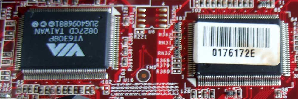
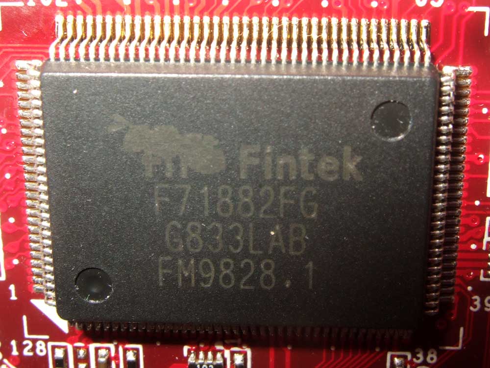
Lower left corner of the motherboard
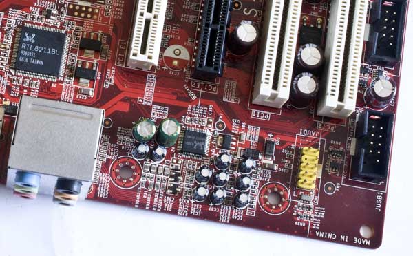
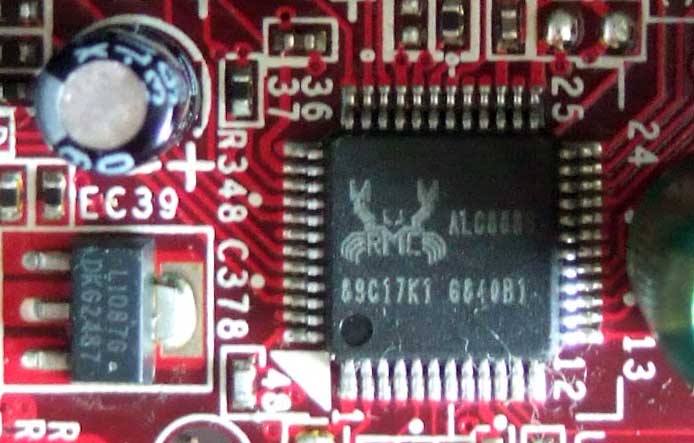
An audio codec with a body kit is traditionally soldered here - this is Realtek ALC888S and this is an excellent 7.1 + 2 audio solution. There is also a standard 9-pin JAUD1 connector for connecting audio connectors on the front panel of the system unit case. And above we see the network controller - Realtek RTL8211BL, it provides LAN 10/100/1000 Fast Ethernet.
Expansion slots
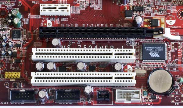
The bottom side of the motherboard is represented by the following connectors: two groups of contacts that support four USB ports on the external brackets or on the front panel of the case. One JSPD1 and this is S/PDIF output. One connector 1394_1 and it is used to connect IEEE 1394 (FireWire or i-Link) on an external bracket. Above are two PCI slots. Then one slot for a PCI Express x16 video card, and one “short” PCI Express x1.
NVIDIA MCP73PV motherboard chipset
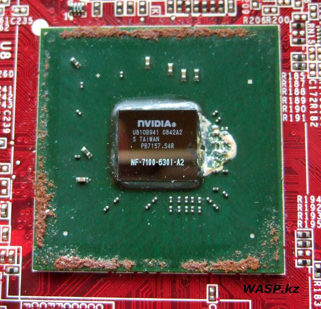
What chipset is the MSI MS-7504 motherboard based on... We remove the heatsink from the chipset - one spring-loaded latch (or clip) breaks - the plastic has become brittle due to time or exposure to temperature... On the “bare” crystal is engraved: NVIDIA U810B941 0842A2 S TAIWAN PB7157.S4R NF-7100-6301-A2. This is the NVIDIA MCP73PV chipset - very interesting. We will write a separate article about it. Let's say briefly: this is the nForce 630i chipset for the Intel platform, as said before - support for single-channel RAM mode standard DDR2. Various video outputs... Lack of PureVideo technology (when part of the work of the video adapter is performed by the processor). IGP - this chipset integrates the GeForce 7100 GPU, which supports all the functions of the discrete video card of the same name... we'll talk about this a little later - in the second part of the article.
External motherboard interfaces
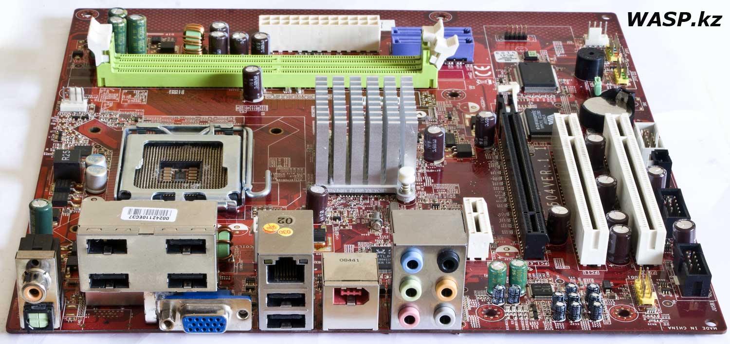
The outputs on the rear panel of the case are as follows: two S/PDIF outputs - coaxial (tulip) and optical. Six USB2.0 ports and one D-Sub video output, also known as VGA. One RJ45 - network connector. One IEEE 1394 port. Six 3.5 mm mini-jack audio connectors. As you can see, there are no PS/2 connectors for mouse and keyboard; you need to use USB solutions...
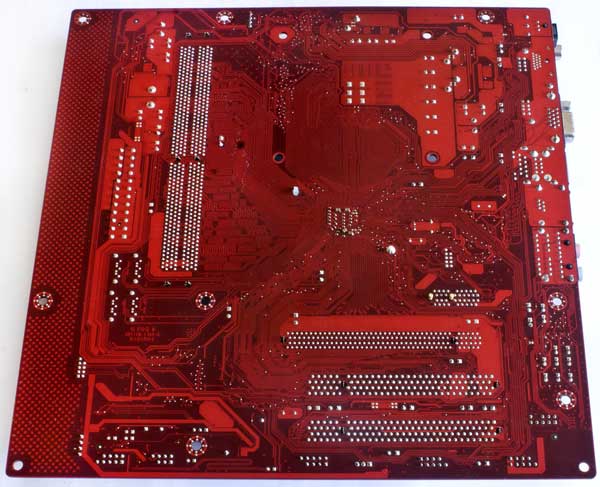
The reverse side of the MSI MS-7504 motherboard and there is nothing interesting here... There is a marking P&Q E162264 - manufacturer of the "bare" printed circuit board...
Characteristics of MSI MS-7504, which are not mentioned in the article:
- Supports Intel Core 2 Quad, Core 2 Duo, Pentium and Celeron LGA775 processors
- System bus FSB 1333 MHz
- NVIDIA MCP73PV chipset
- Memory DDR2 533/ 667/800 SDRAM (240pin/ 1.8V), two slots for 4 GB maximum
- Support LAN 10/100/1000 Fast Ethernet
- Supports IEEE 1394 on two ports, data transfer rates up to 400 Mbps
- Eight-channel audio, meets Azalia 1.0 specification
- Four SATA ports, supported by chipset
- Support for RAID 0/ 1/ in 0+1 mode

The back panel of the motherboard is not just made from a piece of stamped steel... A steel base. A thick steel plate is glued onto the front side, on which the interface designation is printed...

And on the inside there is a layer of foam rubber and a shielding metallized fabric on top of it. Why are these complications necessary? No one knows! But in any case, this affects the cost of the product.
This concludes the first part of the article about this motherboard. In the second part we will describe the operation of the motherboard - BIOS settings, operating features, try tests... and sum up the general results.
Mikhail Dmitrienko, WASP.kz
Almaty
16.03.2024 |

